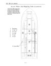
Three trips to the boat with an endoscope over three days and I still couldnt find the entrance to the rigging tubes. Today I lay on my back studying where I was going to have to cut a hole in the binnacle to see into the heart of darkness where wires go, and I had a "you dont suppose" moment. Could there be an access hatch inside the sleeping berth? Popped my head in there for the 2nd time since buying the boat and there was a hatch, and its lid was off and laying on the cushion. No way!. I shone a light in there and behold, there were the entrances to the two rigging tubes. What a relief. It then became childs play to snake a plastic fish down the tube to measure the length of teleflexes I will need. Grady had told me 22' and I was relieved when my measurements confirmed that.
Before I pull that new teleflex though I need to understand how many electrical cables I will need to run with it (in addition to thee wiring harnesses), from the battery to the bus in the helm, and what the wire gages are. Does anyone know if Grady provides wiring diagrams for the vintage years? Mine is a 1997.
One additional question just occurred to me. On the back of the transom there is a stainless tube from which the teleflex, fuel line, wiring harness all will exit. I understand that enough slack must be in them to allow the engine to tilt up and down and left right for steering, Is there supposed to be a rubber sleeve inside that stainless tube that secures the bundle in place so it doesnt slide in and out as the motor moves? Alternatively is there supposed to be a teflon sleeve to allow the bundle to move in and out a bit? If anyone knows the answer I would appreciate it so i can order the part or fabricate what I need.
Thanks so much for your patience with my questions. The data base of knowledge from people on this forum is awesome.
I expect in a very short period of time it will be possible for AI to to scan the entire contents of this forum, and instantly answer questions. This website is a gold mine of data. I am going to make a donation tonight.
Last edited:


