Exploring battery set up and charging options

kirk a

Well-Known Member
Joined
Sep 26, 2009
Messages
403
Reaction score
132
Points
43
Location
Massachusetts
Model
Express 330
Considering changing the battery configuration from the stock 330 set up with a 2 bank system. Reason: occasionally lose electronics when restarting an engine while fishing due to voltage drop. I'd like to have the confidence to shut motors off when offshore overnight.

Possible configuration is a 3 bank system; one battery dedicated to starting each motor, and a parallel pair for the house. This should provide more power for longer duration for running electronics.

One question I have - in the stock set up one bank is tied to the windlass, and the other is tied to the thruster. Those are the two largest draws if used. In reality, I've yet to use the windlass for anything other than testing it. Is there any risk in tying both of these to the house bank? Neither would be used without motors running.

There are at least two ways to ensure charging of the house bank. First is using the aux charging ability of the Yamaha's. Second is using an ACR. I'm very familiar with Blue Seas ACR, as I installed this on my last boat. I've not had the ability to have an aux charger previously.

Another question - if going the ACR route, it appears that the existing 2 bank charger can be used, as once either starting battery is up to 13.x volts, the house will be charged. This says that a new charger is not required. This seems to swing the choice towards the ACR, as the house bank will always be charged via the ACR, which is not true of using the aux charger from the motors - the house only charged if motors running. Am I understanding this correctly?

The costs appear similar for both options.
 

Hookup1

GreatGrady Captain
Joined
Oct 16, 2007
Messages
3,039
Reaction score
859
Points
113
Age
70
Location
Cape May, NJ
Model
Islander
I had similar problem with low voltage while fishing in Florida in the Winter. I'm running bait pumps, refrigerator and electronics the whole time I'm out (daytime). I have 4 Duracell AGM batteries (2 starting and 2 house separate not paralleled) and a ProMariner Pro 20 3-bank charger and a Noco single bank charger.

I had a lot of trouble with fuse holders burning up on the earlier ProMariner chargers. They would run hot to the touch, fail and I would find battery dead in the morning. All bait in baitwell dead. Make sure your charger(s) are in fact charging with voltmeter and engines off. Newer smart charger important for AGM profile and to avoid cooking batteries.

I have charging shunts on both engines. Each engine charges it's own starting battery and one house battery. I don't turn my engines off while fishing so the house batteries are always charging.

One house battery handles the boat, electronics, refrigerator and one baitwell. All circuits on original boat. The second house battery is located under the v-berth inside the cabin. This battery handles bow thruster, windlass, stereo amp and a baitwell pump.

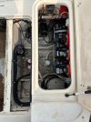
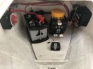
I worked the low voltage problem for several years until I found the right combination. The fuse block and switch in the upper corner of the battery box photo connects to the battery in the forward compartment. The second photo shows the 4th battery, windlass relay and charger. Because it is an enclosed compartment with a battery and charger a non-venting AGM type battery is required.

25 Bait 4.jpeg IMG_0531.jpeg
 

SkunkBoat

Well-Known Member
Joined
Oct 12, 2017
Messages
4,521
Reaction score
1,619
Points
113
Location
Manasquan Inlet NJ
Website
www.youtube.com
Model
Express 265
see this post. You would have room for bigger batteries.
https://www.greatgrady.com/threads/new-battery-config-for-265.25744/

This is my new setup. Four batteries. One 24M starting battery for each motor and a parallel pair of 24DC as the house.
The House charges from the AUX charging cables when either or both motors are running. (new Zukes and old Yammies worked this way). 3 bank ProMariner charger for shore charging.
The House is separated from the starting circuit.(unles switched to help start in an emergency). Starting motors will not blink your electronics.

My winch uses the port starting battery but the motor is running when pulling anchor.
I ran 6 awg feed directly from battery to the winch and use a solenoid to control. Your grady setup might be lame if it is powered from the terminal bus with 10awg.
That will really drop your electronics.

I don't have a bowthruster. I dock a boat like a real man.... ;)

Drift the canyon from dusk to dawn with motors off. No generator. LED floods, UW LEDS, VHF, Sonar, MFD...
Very happy with the setup.

As for the blinky electronics. The House split off will probably fix that.

If you use an ACR you need to use the SI (Start Isolation) or you will still get blinky.

Your 330 is probably a lot different than a 265, maybe a DC breaker panel in the cabin?
but ...also look at batteries, switches, breakers, Fuse panel, switch panel and the terminal busses for vertigris (green corrosion).
Look for possiblitiy that there are too many circuits for the feed wire. An example is my fuse panel is fed from the terminal bus with 10AWG wire. That means the current for everything on the fuse panel flows thru that piece of wire. The more you turn on, the bigger the voltage drop across that piece of wire and fuse panel. If you move a high power thing (radar, autopilot) to the terminal bus with its own inline fuse, it is now fed by the 6 awg wire to the bus. The fuse panel is now less effected.
 
  • Like
Reactions: Chutch

Fishtales

Well-Known Member
Joined
Jan 31, 2005
Messages
8,075
Reaction score
1,300
Points
113
Just curious, has anyone installed a cap bank to hold the voltage up? You may solve a sensitive electronics reset problem for an engine no start problem.
 

Hookup1

GreatGrady Captain
Joined
Oct 16, 2007
Messages
3,039
Reaction score
859
Points
113
Age
70
Location
Cape May, NJ
Model
Islander
That would probably work for older units. Newer units make their own power internally. They can take 12 to 36 VDC without changing a switch. But 10 VDC is the low end of what they can tolerate. My issue has been low voltage alarms.. If you run bait pumps, refrigerator, electronics, stereo, etc all morning without any supplemental charging on a Group 27 battery you will probably have alarms. Older battery and poor charger/charging also a factor. Newer "smart" chargers do a much better job charging to prevent "cooking" the battery.
 

Hookup1

GreatGrady Captain
Joined
Oct 16, 2007
Messages
3,039
Reaction score
859
Points
113
Age
70
Location
Cape May, NJ
Model
Islander
One of my favorite movies along with Jaws!
 

ttles714

Well-Known Member
Joined
Jun 6, 2009
Messages
214
Reaction score
16
Points
18
Location
NJ
My 2001 Marlin with 250 hp OX66's with aux charging cables had a much better system then my 2007 Marlin with F250's... Both with 4 batteries but the older had much better isolation between house and engine batteries ... The OX66's actually had an isolation system built into the engines. So both house batteries were charged independently form the engine starting batteries .. With this Grady also included switches that you could connect a combination of batteries for starting if needed. ... Changing the 2007 is a project that I keep procrastinating on doing !!!
 
Last edited:

kirk a

Well-Known Member
Joined
Sep 26, 2009
Messages
403
Reaction score
132
Points
43
Location
Massachusetts
Model
Express 330
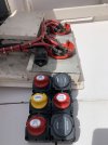
After doing some more thought and research, my current plan is leaning towards a BEP cluster, for the added simplicity over BS. Need to document the current configuration tomorrow and then start planning it. Would like to figure out what to use for a mounting panel that looks as stock as possible and flush mount the BEP cluster, plus the other 4 circuit breakers.
 

kirk a

Well-Known Member
Joined
Sep 26, 2009
Messages
403
Reaction score
132
Points
43
Location
Massachusetts
Model
Express 330
It will be a tight fit, but should work. Little bit concerned about the cables bending enough. Going with a piece of 1/8" black ABS plastic, and flush mounting the BEP and other circuit breakers on it.

IMG_7272.jpeg
 

SkunkBoat

Well-Known Member
Joined
Oct 12, 2017
Messages
4,521
Reaction score
1,619
Points
113
Location
Manasquan Inlet NJ
Website
www.youtube.com
Model
Express 265
That’s a good solution for the 330. You had that panel that came out to a door. On my 265 the switches were way in the back on the transom split on both sides. I would’ve had to rewire everything to move switches Give us a good write up. I don’t think anyone has posted that project yet
 

kirk a

Well-Known Member
Joined
Sep 26, 2009
Messages
403
Reaction score
132
Points
43
Location
Massachusetts
Model
Express 330
That’s a good solution for the 330. You had that panel that came out to a door. On my 265 the switches were way in the back on the transom split on both sides. I would’ve had to rewire everything to move switches Give us a good write up. I don’t think anyone has posted that project yet

Yes, I was unable to find any pictures or write up of this project, which somewhat surprised me. I was able to find a picture where this was done, by looking at older for sale ads for 330's.

Your concern about 1/8" is noted - since the span is short - only aboutr 6" vertically, and 19 wide, there should not be a huge amount of flex. I am prepared for some, and will laminate some supports to it if need be. The piece I have is 12x24 and does flex, but not significantly in the 12" direction. I'll cut it up this week, and post the process.
 
  • Like
Reactions: SkunkBoat

kirk a

Well-Known Member
Joined
Sep 26, 2009
Messages
403
Reaction score
132
Points
43
Location
Massachusetts
Model
Express 330
Got the panel prepped last night.

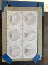
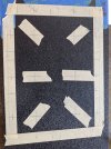
The cluster came with a template for the holes needed. I did not want to destroy it, in case something went sideways with the first attempt, so I used it to lay out the holes needed. I normally work with wood, where it is usually child’s play to layout the information on the piece. Plastic does not allow this, so I went with masking tape. I was also concerned that the template would not adhere well to the plastic.

The center-to-center measurement came out at 2 11/16”, which seemed like an odd number. I checked in metric too, but it was also off – something like 68.5mm.

I marked off the spaces at top and bottom where the panel would be covered by the frame. Then measured the center point and marked it. Identified and marked the center point on the BEP template. Using a square, and center lines, aligned the template to the panel and taped the corners. From here, transferred the centers of the holes to the tape at the perimeter using the square, both horizontally and vertically.

IMG_7282.jpeg

Added tape to the center of the 6 main holes and marked the exact center from the lines on the tape.

IMG_7283.jpeg

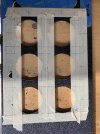
On the drill press, I set up a temporary fence to align the depth. I used a plain drill bit to test for alignment, then once the fence was set, swapped it out for a 2 1/8” hole saw bit. This bit is a shade too big, but the next size down (2”) was too small. The perfect size would be a 2 1/16” bit, but I did not have one – as it turned out, having a slightly oversized hole worked well.

IMG_7284.jpeg

Adjusted the fence for the second row and drilled those out also. The plastic melts a bit as the drill cuts, it is best to remove the disc from the hole saw as quickly as possible, to avoid it getting stuck.

Once the main holes were drilled, the panel was marked for the smaller holes for the bolts to attach. These will be 10-24 sized, which take a 3/16” drill bit.

IMG_7285.jpeg

This was the stopping point.

IMG_7286.jpeg
Next steps are cutting hole for house 50amp breaker, and drilling holes for the 3 other breakers (Memory, Front Float Switch, Rear Float Switch)

Since this panel does flex slightly and the way the BEP cluster is designed, spacers will be required for each bolt on the 4 switches, but the 2 DVSR have ‘shoulders’ and will snug against the panel. I’ll investigate purchasing spacers when getting the hardware but suspect I may have to mill up something from mahogany or starboard.
 
Last edited:

kirk a

Well-Known Member
Joined
Sep 26, 2009
Messages
403
Reaction score
132
Points
43
Location
Massachusetts
Model
Express 330
Cut the holes for the 50 amp breaker with a Dremel, and then drilled out the holes for the other 3 breakers.

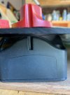
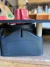
The next puzzle is that with a relatively flexible panel, there are no ‘shoulders’ on the BEP switch boxes to butt against the panel, so the panel will bend when the cluster is bolted on.

Here is a side view of the gap I’m speaking about

IMG_7291.jpeg

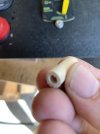
My resolution was to make some custom spacers. Measured the distance between the bolt hole on the BEP and the inside of the panel. From a scrap of wood, cut a piece to the needed length, then drilled a 3/16” hole through it. Mounted it on the lathe and turned it down to approximately 5/16” in diameter to fit in the bolt hole.

Side view with spacer

IMG_7292.jpeg

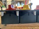
Once the test piece was fitted, I ripped a piece of ¾” PVC trim down to a shade under 15/16”. Drilled a series of holes ¾” apart, then cut each square. Turned these down on the lathe. I was not thrilled with working with the PVC as it moves when it gets warm during turning, and some of the spacers compressed too much. Still considering redoing all of them in mahogany and using that instead. Not really worried about using wood in this location, as it should stay pretty dry.

Spacer alone

IMG_7293.jpeg

Side view with several dry fit

IMG_7296.jpeg

Panel overview

IMG_7287.jpeg

Unless I decide to redo the spacers, the next steps will be installation on the boat. Thinking about that, the design of the cluster will force all the wiring to be connected first, before attaching the cluster to the panel. This will be tricky for a number of reasons. There are 20 something bolts needed to attach the cluster!!! All these bolts need to be aligned and tightened, while fighting the wiring which will wish to prevent the cluster moving as needed.

Overall comments about the BEP cluster

As of now, even if the cluster works 100% as it should, I have to say that I’m not thrilled with the design. As noted above, there are no consistent shoulders for a flush mount. The cluster is simply 6 individual boxes held together with a plastic clip and is somewhat flimsy in nature. Each box is solid, but no effort is put into making it into a solid unit.

The other negative, is that the back of each box is held on by the mounting bolts, which is suboptimal. If one needs to access it, most of the time 4 bolts must be removed. There are 22 bolts to install this cluster, and it feels like most/all are needed with the relatively flimsy nature of the other connections.

The cluster must be wired first and then installed to the panel. My preference would have it set up so that the unit could be secured to the panel, the wiring routed and connected, then the back of the cluster be attached. This way, the wiring could be finalized, secured, and tested before fully assembled.
 
  • Like
Reactions: Chutch

SkunkBoat

Well-Known Member
Joined
Oct 12, 2017
Messages
4,521
Reaction score
1,619
Points
113
Location
Manasquan Inlet NJ
Website
www.youtube.com
Model
Express 265
Overall comments about the BEP cluster

As of now, even if the cluster works 100% as it should, I have to say that I’m not thrilled with the design. As noted above, there are no consistent shoulders for a flush mount. The cluster is simply 6 individual boxes held together with a plastic clip and is somewhat flimsy in nature. Each box is solid, but no effort is put into making it into a solid unit.

The other negative, is that the back of each box is held on by the mounting bolts, which is suboptimal. If one needs to access it, most of the time 4 bolts must be removed. There are 22 bolts to install this cluster, and it feels like most/all are needed with the relatively flimsy nature of the other connections.

The cluster must be wired first and then installed to the panel. My preference would have it set up so that the unit could be secured to the panel, the wiring routed and connected, then the back of the cluster be attached. This way, the wiring could be finalized, secured, and tested before fully assembled.


"my current plan is leaning towards a BEP cluster, for the added simplicity over BS. "

shit never easy is it....
 
  • Like
Reactions: kirk a

kirk a

Well-Known Member
Joined
Sep 26, 2009
Messages
403
Reaction score
132
Points
43
Location
Massachusetts
Model
Express 330
Funny, when I initially wrote that, the thought about jinxing myself went through my mind...

But yes, there is no free lunch. What I would have spent on extra wires for the BS system, I spent on hardware for this one. It is a boat, after all.
 

kirk a

Well-Known Member
Joined
Sep 26, 2009
Messages
403
Reaction score
132
Points
43
Location
Massachusetts
Model
Express 330
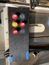
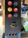
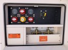
Panel is installed. Had to wrestle a bit with a couple of the cables but eventually they behaved.
Ended up installing the cluster with the bolts on the 3 blocks which did not need wiring work. This provides enough rigidity to work with.
IMG_7302.jpeg
 

Sardinia306Canyon

GreatGrady Captain
Joined
Oct 11, 2023
Messages
559
Reaction score
109
Points
43
Age
60
Location
Island of Sardinia
Model
Canyon 306
Good tread!
On my new 2011 Canyon i still have the original GW setup with twin battery for one engine and electronics together and same as OP, starting the engine the electronics flicker what i consider as No-Go.
Not really sure why GW choose this battery setup other than be able to use only 2 battery switches.

However, i would like to change that too to 2 x starter batteries and one for house, maybe two if i can fit them.
Probably just one 100Ah+ LiFePo but a model with a BMS what allow the LiFePo to be used as starter battery if put in parallel for house use, that would give me plenty of juice.

Any experience with LiFePo for house and emergency staring battery?

Chris