Helm Power Wire Gauge?

HarborHound

Member
Joined
Mar 15, 2018
Messages
10
Reaction score
1
Points
3
With today's power hungry electronics, what gauge wire should be bringing power to the helm?

I have a 2008 282 Sailfish, which has a 12 AWG main cable bringing power to the helm from the battery switch. I'm getting the feeling that its not enough, I estimate I am using at least 16 amps with everything running and the wire is rated for 20 amps. It seems that when there is a spike in usage that the electronics are not getting enough juice.

I have the following 2014 electronics and estimate the amount of amps are:

1) Radar: Raymarine RD424HD Color (5 amps transmitting)
2) Raymarine e95 MFD (1.3 amps)
3) Fusion Stereo MS-RA70 (I believe 3 amps, but its tough to say. Info is scarce. However, I do have a separate amplifier that powers the speakers and is wired independently to the battery switch, so I don't think the stereo draws too much power)
4) Furuno FCV-588 Fishfinder w/ 1kw transducer (1.5 amps, I think)
5) Raymarine Autopilot w/hydraulic pump (estimate 5 amps with pump running)
6) Sirius XM module (amps?)
7) ICOM M330 VHF ( 1 amp receive, 5 amps transmit)

My fishfinder seems to constantly give me a low voltage alarm if I'm not running the engine, even though its getting 12 volts at the wire harness connection when on battery only. The unit is only 1 year old, but the transducer is a 2014. Connections are good.

Batteries are 3 group 31 AGMs.

Thanks for your input.
 

DennisG01

GreatGrady Captain
Joined
Sep 1, 2013
Messages
7,190
Reaction score
1,341
Points
113
Location
Allentown, PA & Friendship, ME
Model
Offshore
Thats not right. That boat had to have 6 gauge from the red button breaker to the terminal block under the dash.

look more closely-er
Agree... and "like" the closely-er :)

I suspect you found the wrong wire... or you are suffering from a disease known as "previous owner syndrome" :)
 

seasick

Well-Known Member
Joined
Aug 19, 2008
Messages
9,531
Reaction score
1,420
Points
113
Location
NYC
Unfortunately the answer isn't simple. There are three main parameters that are needed to size the conductors: The amperage draw, the total length of the round trip run, and the acceptable voltage drop under load. The first is obvious, the second some what obvious but note that the smallest gauge conductor is the limiting factor so increasing the 12V conductor size for more capacity doesn't work if the ground conductor is the same or larger gauge. The total run is the length of the 12v conductor added to the length of the negative conductor so if your device or fuse block is a 15 foot run, the total run is 30 feet.
The third factor is the tricky one. Electronics can be sensitive to excessive voltage drop so the guidelines are that the drop should be no more than 3%. Other types of loads like blowers, windlasses, pumps etc may be designed with a 10% allowable voltage drop. On most smaller boats, the accessory breaker near the batteries may feed both mechanical loads as well as electronic devices. It is a common complaint that some boaters experience there MFDs rebooting or shutting off when a large current demand from a mechanical load is called for. So it is wise to understand each situation.
Some times a boater will have no issues but adding an additional load finds that strange things are happening to electronics.

Running new feeds directly off of the battery or battery switches is one way to separate heavy mechanical loads from electronics power. A common situation may be a windlass that can draw a lot of current or the installation of a high power stereo.

The fact that you may have a 30 amp breaker doesn't necessarily mean that you can draw a constant 30 amps. I prefer to size for 80 to 90% load so on a 30 amp circuit, the max current I would sped is 24 to 27 amps.
 

Hookup1

GreatGrady Captain
Joined
Oct 16, 2007
Messages
3,035
Reaction score
855
Points
113
Age
70
Location
Cape May, NJ
Model
Islander
Don't trust the unit for voltage reading. Put a good voltmeter on both ends to really see what voltage you have.
 

HarborHound

Member
Joined
Mar 15, 2018
Messages
10
Reaction score
1
Points
3
Correct, yes there is a larger gauge wire feeding the entire helm. I was incorrectly thinking that the wire powering the fuse block for my electronics went all the way back to the battery fuse area.

Good advice, Seasick, as well. Thanks.

So, what I have is a 6 gauge main power line feeding a bus bar, which in turn has a 12 gauge wire feeding a fuse block that powers my electronics (as listed in the first post). Therefore, I still have roughly 16 amps feeding off a fuse block fed by a 20 amp max wire (its only about 2 feet from bus bar to fuse block).

I'm thinking I have two options - first, try running a 10 gauge wire from the main bus bar to the electronics fuse block. Or, maybe better, run an independent 6 gauge wire directly back to the battery switch fuse board, which will only power the electronics. Thereby isolating the electronics from interference by the windlass, ignition switch, macerator pump, etc.

What do you guys think?

Dennis - I will check again, but I believe the last I checked the fuse block that powers the Fish Finder with a voltmeter I was getting 12.2 volts.

Thanks all.
 

seasick

Well-Known Member
Joined
Aug 19, 2008
Messages
9,531
Reaction score
1,420
Points
113
Location
NYC
I have a 2008 282 Sailfish, which has a 12 AWG main cable bringing power to the helm from the battery switch. I'm getting the feeling that its not enough, I estimate I am using at least 16 amps with everything running and the wire is rated for 20 amps. It seems that when there is a spike in usage that the electronics are not getting enough juice.


My fishfinder seems to constantly give me a low voltage alarm if I'm not running the engine, even though its getting 12 volts at the wire harness connection when on battery only. The unit is only 1 year old, but the transducer is a 2014. Connections are good.


15 amps on a 12G conductor will have a greater than 3% voltage drop if the round trip cable run exceeds 10 feet! That s a straight run of only 5 feet. If indeed your accessory conductor is 12 G it is way undersized. For 15 amps on a 30 foot round trip run, you would need an 8 G minimum

Here is a link to the Marinco site for cable sizing.
 
  • Like
Reactions: HarborHound

Hookup1

GreatGrady Captain
Joined
Oct 16, 2007
Messages
3,035
Reaction score
855
Points
113
Age
70
Location
Cape May, NJ
Model
Islander
Check the voltage at the 6awg wire, at the 12awg wire and at the fuse block. Also check voltages on the "hot" side of the fuse - the one that goes to each unit. Check with the units on to load the circuit.

Also check and clean all grounds.

You shouldn't be having problems that require running a new #6 power and ground wire. I have seen corrosion on the fuses, terminals, slip on connectors and bad grounds.
 

HarborHound

Member
Joined
Mar 15, 2018
Messages
10
Reaction score
1
Points
3
Gotcha. Thanks Hookup, I will to do some testing with my voltmeter and see what I find. I'll report back when I can.
 

DennisG01

GreatGrady Captain
Joined
Sep 1, 2013
Messages
7,190
Reaction score
1,341
Points
113
Location
Allentown, PA & Friendship, ME
Model
Offshore
The rating for a particular wire is only in part based on it's size. The length of the run is also a factor. For that 2' run, 12g is totally fine. But you can double check by using a wire size calculator - Blue Seas is a reliable source.

12.2... yeah, that's low. I'm not surprised it's complaining. Gotta figure out WHY it's so low. What do you measure at the battery? There could also be dirty connectors... corroded (internally) wires... etc, all factoring in here.
 

SkunkBoat

Well-Known Member
Joined
Oct 12, 2017
Messages
4,508
Reaction score
1,614
Points
113
Location
Manasquan Inlet NJ
Website
www.youtube.com
Model
Express 265
I'm surprised you say there is 12awg from terminal bus to the fuse block. Typically it is 10 awg. Also a single 10 awg to the switch panel breakers.
I recommend running the higher amp things like Radar and AP to the bus bar with inline fuses, not to the fuse block. That includes the negative wires to the negative terminal bus.
High watt stereo amps are a problem but you say its direct to battery so thats good. My AP specifies its own switchable feed to the battery via an inline fuse.

Also, typically there is a 10 awg up to the hardtop fuse panel. That gets over loaded with added stuff. Don't power radar from there. The spreader lights are powered from there. Swap them to LED asap if you haven't already. I highly recommend removing and inspecting the backside of the fuse blocks and all of the fuses. By now there are green corroded connections and blades of fuses that cause a voltage drop across them and heat up to the point of melting the plastic. These are the gremlins that cause your electronics to blink out or give low voltage errors.
 
  • Like
Reactions: HarborHound

HarborHound

Member
Joined
Mar 15, 2018
Messages
10
Reaction score
1
Points
3
Thank you both. Sounds like I need to do some digging around. Being that the boat is 15 years old, corrosion seems a likely culprit.
 

HarborHound

Member
Joined
Mar 15, 2018
Messages
10
Reaction score
1
Points
3
Which begs another question - if my boat is 15 years old and most of the wiring is original. When do you think I'm at the point where I need to consider completely re-wiring the boat?
 

Hookup1

GreatGrady Captain
Joined
Oct 16, 2007
Messages
3,035
Reaction score
855
Points
113
Age
70
Location
Cape May, NJ
Model
Islander
You don't want to re-wire the boat. There a lot of older boats on this site that are working fine.

Look at the connectors on the 6 AWG wire. Red and black. If the terminal looks bad or the copper wire is black replace it. If these wire get wet with saltwater they wick up inside and corrode the copper. Marine wire should be tinned (silver). Cut back until you get clean wire or replace the wire.

How many watt amp are you using? How is that wired? I ran mine directly to the battery. Make sure all your battery connections are good.

Also consider swapping your Group 31's. How old are the batteries and what kind of charger are you using? You should have 12.8 VDC battery voltage after a fresh charge and about 13.4 VDC while the charger is charging. Don't waste your time with a bad battery. Make sure your engine is charging the house battery. You should see similar voltages to above with motor running/not running and shore charger off.

It's a guess but I suspicious of your battery health and charging system.
 
Last edited:
  • Like
Reactions: SkunkBoat

HarborHound

Member
Joined
Mar 15, 2018
Messages
10
Reaction score
1
Points
3
Ok, well I'm glad to know I don't have an imminent re-fit for the wiring coming up.

Amp for the stereo? Its wired on its own, directly to the battery switch fuse panel.

Agreed on the Batts. One of them was purchased last season, Odyssey Group 31. In progress of replacing the 2 that are from 2019, with Odyssey's. I hate to spend that much money, but like you said - I don't want to risk wasting time with bad batteries. I have a promariner charger for all 3 batteries.
 

Hookup1

GreatGrady Captain
Joined
Oct 16, 2007
Messages
3,035
Reaction score
855
Points
113
Age
70
Location
Cape May, NJ
Model
Islander
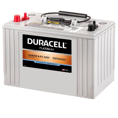
I have been using Duracell AGM's from Sam's Club for several years now. They have a Group 31 AGM Marine. I'm using 3 - 34's and a 27. Great price and no problems.


The ProMariner charges are fine. Depending on the model and age you need to be careful with the fuses. Sometimes they overheat, melt the fuse holder and pop the fuse. You think you are charging when you are not. Check to see that you have 13.4 VDC on all three banks when charging. Fuse holder usually destroyed and can be replaced.

ProMariner went to new fuse holders a year or two back.
 
Last edited:
  • Like
Reactions: HarborHound

SkunkBoat

Well-Known Member
Joined
Oct 12, 2017
Messages
4,508
Reaction score
1,614
Points
113
Location
Manasquan Inlet NJ
Website
www.youtube.com
Model
Express 265
" directly to the battery switch fuse panel." please explain or show picture of this

You should not need to change the 6awg Red and Black wires running from battery compartment to under helm. You should check/re-make the terminal loops at the battery/battery switches/red button breaker.
For gods sake replace the red button with an MRCB or Bussman 185 style breaker.

Your macerator is not running all the time so its not a major culpret unless the problem occurs when you run the pump.
Your windlass SHOULD have its own 6awg pos & neg feed and 25A breaker. I don't have an OEM windless on my Grady but it has a prewired 10awg feed from the terminal bus forward to the anchor locker.
I assume that was for switched power to a solenoid to run the windlass. (thats what I'm going to use it for) I don't THINK Grady ran a windlass on a 10awg feed from the fuse panel. That would be dumb.
 
  • Like
Reactions: Hookup1

Hookup1

GreatGrady Captain
Joined
Oct 16, 2007
Messages
3,035
Reaction score
855
Points
113
Age
70
Location
Cape May, NJ
Model
Islander
I assume that was for switched power to a solenoid to run the windlass. (thats what I'm going to use it for) I don't THINK Grady ran a windlass on a 10awg feed from the fuse panel. That would be dumb.
My Islander had a factory Horizon 700 windlass on it. It had maybe 10 AWG wire from battery to a panel switch to windlass with no solenoid. When I installed my Lewmar I used the original wires from the helm to control the new solenoid and powered the windlass from the forward battery with the bow thruster.

Not clear if HarborBound is setup the same way.

I really should change my red button breakers out too. Thanks for the reminder.
 

seasick

Well-Known Member
Joined
Aug 19, 2008
Messages
9,531
Reaction score
1,420
Points
113
Location
NYC
Too much thinking going on. If it is true that the accessory feed is 12G. That feed is sized too small. It's as simple as that based on your load stats.Yes, there could be other issues but the correctly sized conductor should be the first task.
As to the question as to whether you need or want to rewire, my answer is NEVER:) It is a far more arduous task than you might imagine. Even if you need to run a few new wires, you usually just leave the old ones in place. When the boat is made, all harnesses are installed before the deck mold is glued/bolted to the hull mold
 
  • Like
Reactions: HarborHound