I/O conversion to outboard

Keller22

Member
Joined
Jul 11, 2021
Messages
9
Reaction score
3
Points
3
Model
Seafarer
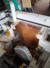
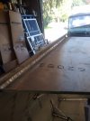
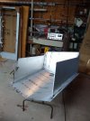
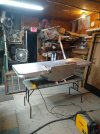
I have a 1986 228 seafarer, which I'm converting to a outboard. Before everyone posts how hard it is, I know I've already replaced the transom, floors and glass in the key hole. I'm going to be building the bracket from scratch and I'm looking for some pictures and dimensions of their brackets. Any tips would be appreciated. Thanksboat 3.jpgboat1.jpgboat2.jpg
 
  • Like
Reactions: PointedRose

blindmullet

Well-Known Member
Joined
Oct 19, 2015
Messages
449
Reaction score
106
Points
43
Location
Florida
Model
Explorer
What was your layup schedule for the inside of the transom?
 

Keller22

Member
Joined
Jul 11, 2021
Messages
9
Reaction score
3
Points
3
Model
Seafarer
What was your layup schedule for the inside of the transom?
I replaced it with 2 layers of 3/4 marine plywood and epoxied them together. Then added 2 layers of chop strand mat and 1 wolven.
 

DennisG01

GreatGrady Captain
Joined
Sep 1, 2013
Messages
7,190
Reaction score
1,341
Points
113
Location
Allentown, PA & Friendship, ME
Model
Offshore
I'm not sure if you'll find anyone that built their own bracket - or at least I haven't seen anyone talking about that. But, if you're building your own... why does it matter what someone else did? Make it the way YOU want it, you know? To get a rough idea of length, just compare to brackets that are commercially available - and those are easy to find/look at on the net and companies websites.

If you're building it out of glass, it's going to add even more weight back there (than the aluminum ones) and the scuppers will be even more under water.

You're going to want to strengthen up your transom, transversely. Even tie it into the stringers with knee walls, or similar.

The woven you used... was it just lightweight woven or something like 1708?
 

Keller22

Member
Joined
Jul 11, 2021
Messages
9
Reaction score
3
Points
3
Model
Seafarer
I'm not sure if you'll find anyone that built their own bracket - or at least I haven't seen anyone talking about that. But, if you're building your own... why does it matter what someone else did? Make it the way YOU want it, you know? To get a rough idea of length, just compare to brackets that are commercially available - and those are easy to find/look at on the net and companies websites.

If you're building it out of glass, it's going to add even more weight back there (than the aluminum ones) and the scuppers will be even more under water.

You're going to want to strengthen up your transom, transversely. Even tie it into the stringers with knee walls, or similar.

The woven you used... was it just lightweight woven or something like 1708?
I'm trying to find the how much the bottom of the bracket slopes up. That's the thing I'm having trouble finding. The rest I can figure out. The backets going to be made out of 1/2 and 3/8 aluminum plate 6061. I'm going to tie the transom into the stringers. Should be plenty strong. I don't remember what mat I used but it wasn't light weight.
 

DennisG01

GreatGrady Captain
Joined
Sep 1, 2013
Messages
7,190
Reaction score
1,341
Points
113
Location
Allentown, PA & Friendship, ME
Model
Offshore
You can see my signature...

The boat is in the water and I'm not sure if I have any good pics of that area - but as I mentioned, look to commercially available brackets for ideas.
 

blindmullet

Well-Known Member
Joined
Oct 19, 2015
Messages
449
Reaction score
106
Points
43
Location
Florida
Model
Explorer
You should have a good 3 layers of 1708/1808 with some tabbing on the inside.
 

Keller22

Member
Joined
Jul 11, 2021
Messages
9
Reaction score
3
Points
3
Model
Seafarer
You should have a good 3 layers of 1708/1808 with some tabbing on the inside.
There's many ways to skin a cat. What I did was stronger than what they did from factory. They only had one layer of glass, maybe 2. I'm also putting 3in by 3/8 aluminum backing plates to help distribute the load.
 

Holokai

GreatGrady Captain
Joined
Aug 14, 2019
Messages
317
Reaction score
136
Points
43
Location
Hawaii
Model
Adventure
Armstrong now makes the stock brackets for the 228s. On a 2017 229 the setback is about 33", pod width is 19", and height is 16" on the sides to about 18" centerline (all measured against the transom). The pod tapers toward the stern but I didn't get the measurements. Most brackets now have a sealed flotation chamber to help offset the engine being set further back. Keep the swim platform set in at least 3" from the sides of the hull to prevent water from touching it (drag) when on plane. General rule of thumb for engine setback is 1" per foot of boat so I'm not sure how Grady pulled it off with the Armstrong bracket but the new 228s ride really well in rough water. Engine mounting height can be looked up online with general stuff like "add 1" for every foot of setback and mount the bracket 24" from the keel at centerline for a 25" shaft motor. I'd take those as general rules and try to get the anti-ventilation plate height correct at the middle set of holes on the engine for your end setback to allow for fine tuning after installation. You're young (from your profile) so you'll probably do well with Googling for more info.

Nice work with patching the transom; it speaks a lot to your commitment and skill set. Not sure how you are with metal fabrication and what scale of shop/tools you have so I would recommend looking at the total projected cost of a homemade bracket (including raw materials, consumables, and final powdercoating, etc.) compared to a commercially made bracket from Stainless Marine, A&J Marine, or Armstrong Nautical. You might be better off with one of the pre-fabricated brackets from a money/time perspective and you'll be leveraging the experience they have from building hundreds or thousands of brackets. Lead times range from 3-6 months when I checked in July and costs range from $2300-$4000+.

Good luck and keep us posted on your progress!
 

Keller22

Member
Joined
Jul 11, 2021
Messages
9
Reaction score
3
Points
3
Model
Seafarer
Armstrong now makes the stock brackets for the 228s. On a 2017 229 the setback is about 33", pod width is 19", and height is 16" on the sides to about 18" centerline (all measured against the transom). The pod tapers toward the stern but I didn't get the measurements. Most brackets now have a sealed flotation chamber to help offset the engine being set further back. Keep the swim platform set in at least 3" from the sides of the hull to prevent water from touching it (drag) when on plane. General rule of thumb for engine setback is 1" per foot of boat so I'm not sure how Grady pulled it off with the Armstrong bracket but the new 228s ride really well in rough water. Engine mounting height can be looked up online with general stuff like "add 1" for every foot of setback and mount the bracket 24" from the keel at centerline for a 25" shaft motor. I'd take those as general rules and try to get the anti-ventilation plate height correct at the middle set of holes on the engine for your end setback to allow for fine tuning after installation. You're young (from your profile) so you'll probably do well with Googling for more info.

Nice work with patching the transom; it speaks a lot to your commitment and skill set. Not sure how you are with metal fabrication and what scale of shop/tools you have so I would recommend looking at the total projected cost of a homemade bracket (including raw materials, consumables, and final powdercoating, etc.) compared to a commercially made bracket from Stainless Marine, A&J Marine, or Armstrong Nautical. You might be better off with one of the pre-fabricated brackets from a money/time perspective and you'll be leveraging the experience they have from building hundreds or thousands of brackets. Lead times range from 3-6 months when I checked in July and costs range from $2300-$4000+.

Good luck and keep us posted on your progress!
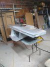
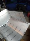
Thanks for the info. I've starting building the bracket already, but everything you said matches up to what I've done. I started it using CAD (cardboard aided design) lol, I went through 3 different designs before I settled on the one in the pictures. I'll post more pictures and dimensions as I go along in the building process.
 

Attachments

  • boat 4.jpg
    boat 4.jpg
    348.8 KB · Views: 57
  • Boat 5.jpg
    Boat 5.jpg
    426.4 KB · Views: 55
  • Boat 7.jpg
    Boat 7.jpg
    384.3 KB · Views: 58
  • boat 6.jpg
    boat 6.jpg
    520.8 KB · Views: 56

DennisG01

GreatGrady Captain
Joined
Sep 1, 2013
Messages
7,190
Reaction score
1,341
Points
113
Location
Allentown, PA & Friendship, ME
Model
Offshore
Nice - I like the use of the "CAD" technology... ;)

Couple quick thoughts - knee walls are nice - but from the pics, the glass looks lightweight. You'll want AT LEAST 1 layer of 1708 there.

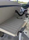
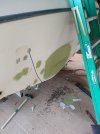
Here's some info you'll probably find info - these are pics of my boat during restoration. The changeover from I/O to OB was done before I got the boat, but the hole in the cockpit floor for the I/O was never addressed by the previous owner. I had found some soft spots so I ripped out the entire floor and rebuilt, fixing the I/O "hole", as well. It ain't super pretty, but my goal was structural soundness, not necessarily cosmetic.


Just realized there's a good pic of the bracket, too.
 

Keller22

Member
Joined
Jul 11, 2021
Messages
9
Reaction score
3
Points
3
Model
Seafarer
Nice - I like the use of the "CAD" technology... ;)

Couple quick thoughts - knee walls are nice - but from the pics, the glass looks lightweight. You'll want AT LEAST 1 layer of 1708 there.

Here's some info you'll probably find info - these are pics of my boat during restoration. The changeover from I/O to OB was done before I got the boat, but the hole in the cockpit floor for the I/O was never addressed by the previous owner. I had found some soft spots so I ripped out the entire floor and rebuilt, fixing the I/O "hole", as well. It ain't super pretty, but my goal was structural soundness, not necessarily cosmetic.


Just realized there's a good pic of the bracket, too.
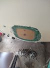
I feel your pain with the floor, I had to replace the middle sections they were a little soggy. Luckily the side sections are still solid. I'll keep the extra layer of 1708 in mind. The pictures will definitely help out. Thanks
 

Keller22

Member
Joined
Jul 11, 2021
Messages
9
Reaction score
3
Points
3
Model
Seafarer
Little update to anyone that's interested. The brackets almost fully welded out. Almost ready to be mounted on the boat.IMG_20210911_153502610.jpgIMG_20210915_182600554.jpgIMG_20210910_193136834.jpgIMG_20210910_193158758.jpgIMG_20210915_182609425.jpg
 
  • Like
Reactions: PointedRose

blindmullet

Well-Known Member
Joined
Oct 19, 2015
Messages
449
Reaction score
106
Points
43
Location
Florida
Model
Explorer
Looks good. How wide? When I had mine built he added some gussets and built out a spot for the dive ladder. If you need any pics I can grab some this weekend.

Are you going with paint or powder coat? I have PC and would have painted if I was doing the work.
 
  • Like
Reactions: Keller22

Keller22

Member
Joined
Jul 11, 2021
Messages
9
Reaction score
3
Points
3
Model
Seafarer
The width is 30 inches. More pictures on this thread will be better for people in the future. I plan in gusseting it more, so I can put a kicker on as well. I'm most likely going to paint it, but I'm going to leave it the way it is for a year to keep an eye on the welds and make sure everything's happy before i paint it. I should add its not going to see salt water only fresh for now.
 
  • Like
Reactions: PointedRose

blindmullet

Well-Known Member
Joined
Oct 19, 2015
Messages
449
Reaction score
106
Points
43
Location
Florida
Model
Explorer
PXL_20210720_143929146.jpg
You can see in the pic he added a larger piece so I could mount the ladder.
 
  • Like
Reactions: Keller22