My next project!!

Hookup1

GreatGrady Captain
Joined
Oct 16, 2007
Messages
3,039
Reaction score
859
Points
113
Age
70
Location
Cape May, NJ
Model
Islander
Wire it with jumpers just like the Nav/Anchor light.

View attachment 33875
That is probably right for nav/anchor light... Nav light are a little different in that they use two wire and reverse polarity to switch both or anchor light (diode in light). Although on small boats I'm not sure it matters.

For wipers it's different. One double pole powers the starboard wiper motor in either "on" position. The other double pole only powers the port wiper motor in one "on" position.

Try this... Jumper wire... 4 to 6. One wiper motor to 1 and the other to 4. 1 and 3 jumpered. 2 and 5 jumpered and connected to 12v. You may have to flip 4 and 6 them to get starboard/both.
 
Last edited:

SkunkBoat

Well-Known Member
Joined
Oct 12, 2017
Messages
4,521
Reaction score
1,619
Points
113
Location
Manasquan Inlet NJ
Website
www.youtube.com
Model
Express 265
Same thing. Your just using different pins to do the same thing.
and there is no reverse polarity involved in any case. It just puts +12V on the output pins. And no need for a diode with a DPDT switch with jumpers

That diagram does pin 3 Nav & Anchor, pin 1 Anchor only. So just make it Both/OFF/Single.
Looking at your switch cover, Stbd is down, Both is up.
Put the Starboard wiper motor on pin 1.
 
Last edited:

SkunkBoat

Well-Known Member
Joined
Oct 12, 2017
Messages
4,521
Reaction score
1,619
Points
113
Location
Manasquan Inlet NJ
Website
www.youtube.com
Model
Express 265
KY might have a 10 pin DPDT which provides separate illumination for Up and down positions. That will throw some confusion into the mix. There are jumpers for Illumination also.
NewWire has a diagram https://newwiremarine.com/wp-content/uploads/2018/07/DPDT-switch-powering-two-loads.pdf

I have this switch for my Livewell Manual/off/Timer. Like this diagram, it is not jumpered for a "BOTH" condition.
In addition to all of the illumination jumpers, you would also use a pin 1 to pin 6 jumper to get "Both". Your outpouts would be on pin 1 (down-STbd wiper) and pin 3 (up- Port wiper)
 

Fishtales

Well-Known Member
Joined
Jan 31, 2005
Messages
8,075
Reaction score
1,300
Points
113
That's some nice wiring work for sure.
 

Fishtales

Well-Known Member
Joined
Jan 31, 2005
Messages
8,075
Reaction score
1,300
Points
113
  • Like
Reactions: Stephnic

Ky Grady

GreatGrady Captain
Staff member
Joined
Mar 1, 2006
Messages
3,031
Reaction score
1,353
Points
113
Location
Berea, KY/Cross, SC
Model
Seafarer
Skunk is correct. I have the 10 pin switch. Using the reference he provided, I will take a look at my switch and see how it's been wired. I also have a position/park wire to contend with also from original wiring from Grady. Appreciate all the help folks.
 

Ky Grady

GreatGrady Captain
Staff member
Joined
Mar 1, 2006
Messages
3,031
Reaction score
1,353
Points
113
Location
Berea, KY/Cross, SC
Model
Seafarer
On a side note, I just ordered 20 of these to use on my side console trim screws. The cap and bases I bought previously never seem to mate up. For $9 to my door, figured I'd give them a shot.

Screenshot_20240526_102435_Chrome.jpg
 
  • Like
Reactions: Halfhitch

Hookup1

GreatGrady Captain
Joined
Oct 16, 2007
Messages
3,039
Reaction score
859
Points
113
Age
70
Location
Cape May, NJ
Model
Islander
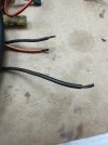
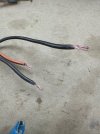
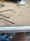
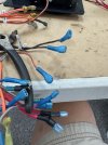
Went over the original wiring harness today. Everything was working before but it's hard to believe given the amount of corrosion on the wire. GW didn't use tinned wire in 1997. All the copper wire is black. But I found a way to use a Dremel tool with a wire wheel to clean the wires up. I then coat with rosin flux and tin them with solder. Solder doesn't wick up that the wire and the adhesive heat shrink keeps it stiff anyway.

Wire 1.jpeg Wire 2.jpeg Wire 3.jpeg Wire 4.jpeg

Replaced all the old connectors. Panel is assembled and harness connected. Some ty-wrap work before installing it in the boat.
 
Last edited:
  • Like
Reactions: Halfhitch

Hookup1

GreatGrady Captain
Joined
Oct 16, 2007
Messages
3,039
Reaction score
859
Points
113
Age
70
Location
Cape May, NJ
Model
Islander
Thats a style of switch I have not seen before.
The switch bases are the same as the ones you bought except they use a different switch cover (Contura XIV). They are more rectangle and not as curved. The big differences mine are set in a "frame" mounting panel from Carlon. It hold the stray light in better and doesn't splash light all over the dash. NewWire sells all this. It was a project to have them build it this way but it turned out good.

I went with the low-light red illumination. I don't find it too bright. Only issue is seeing bilge lights during daytime. I'm experimenting with different lighted switches but may go to panel light and/or alarm buzzer when bilge pump runs. I have a high water alarm that I want to integrate somehow too.
 
Last edited:

Hookup1

GreatGrady Captain
Joined
Oct 16, 2007
Messages
3,039
Reaction score
859
Points
113
Age
70
Location
Cape May, NJ
Model
Islander
So I wasn't liking the daytime visibility of the indicator lights for the bilge pumps. I ordered "bright red" switches, took them apart for the LED and installed them in the other switch bases. Nice and bright compared to the "red" backlight LED.

Switch 1.jpeg Switch 2.jpeg Switch 3.jpeg
 
Last edited:
  • Like
Reactions: Ky Grady