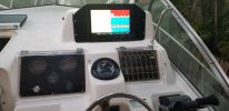
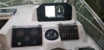
New Electronics in '97 Sailfish 272.

Richard1572

GreatGrady Captain
Joined
Apr 26, 2008
Messages
59
Reaction score
9
Points
8
Location
Homestead, FL
Model
Sailfish
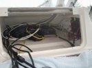
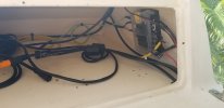
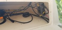
Small change in plans. I decided to move the ring terminal located on the battery for that unswitched power in the overhead console to the house battery switch. That will make that power switched on the house side. Then I located where those wire are running through the chase and up under the dash. I then cut and routed those wires to run up to the console on the dash and will use them to power a new fuse block to run my electronics. Those wires are pretty hefty (I’m guessing 10 or 12 AWG) and I thought it would be a good idea to put all my Garmin equipment (MFD and Radome) on the same dedicated run to the battery (except for the fuel flow sensors). Anyone see any issue with getting my power this way?

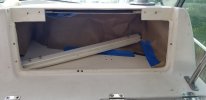
Also, there are a few things I may want to access in the future on the back of the Garmin MFD. USB port, HDMI port and SD card slot. It would be nice to be able to access these without having to break the seal on the dash. A while back I replaced my cockpit and transom pop out inspection ports with screw in style. I think they are a little more secure, but I still have my old inspection ports. I was thinking of making a cutout in the bottom of the console and installing one of the inspection ports from the underside. I could then access the back of the MFD simply by removing one of the panels in the head. Anyone done anything like this or have thoughts? Would there ever really be a need to access the SD card? Generally, I will always have WiFi connectivity. I still need to transfer my waypoints from my old GPSMap to this new unit but will be a onetime deal.
 

Hookup1

GreatGrady Captain
Joined
Oct 16, 2007
Messages
3,035
Reaction score
855
Points
113
Age
70
Location
Cape May, NJ
Model
Islander
I use the microSD cards slots on the back of my 943xsv. I have a G3 VUS513L chart chip for shaded relief imagery and a Active Captain card. I pretty much leave them there all the time.

But I do waypoint swaps for my NJ summer and FL winter trip using HomePort and a SD card (SAVE_TO_CARD and REPLACE_FROM_CARD). I installed the Garmin dual SD card reader so I don't have to get to the back of the unit. This gives me a 3rd and 4th SD card slot.
 

SkunkBoat

Well-Known Member
Joined
Oct 12, 2017
Messages
4,508
Reaction score
1,614
Points
113
Location
Manasquan Inlet NJ
Website
www.youtube.com
Model
Express 265
Generally the larger Gradys have red and black 6awg running from the battery. Generally, the red to battery switch then 40A red button breaker. They run forward to a Positive and Negative bus bar under the dash. The switch panel is fed from there with orange and a black 10awg. Also a fuse panel under the dash is fed from the bus bar with 10awg orange and black. This feeds things taht are not switched(electronics, NEMA2k,,etc). Often there is a 10awg pair running from the buses to the hardtop fuse block.

Yours sounds different.
I would advise against a main feed smaller than 6awg.
 

Hookup1

GreatGrady Captain
Joined
Oct 16, 2007
Messages
3,035
Reaction score
855
Points
113
Age
70
Location
Cape May, NJ
Model
Islander
The Garmin units all take from 10 to 36 volts in and make their own power (regulated) inside the units. Less sensitive to quality of your power then the old days. I would find where the heavy gauge power comes into the helm and pull off another fuse block for the electronics. Mine is inside the lower electronics box on the right hand side. Fuse block and terminal strip mounted on a piece of starboard that can be removed to make it easier to work on.

4210c.jpg
 

Richard1572

GreatGrady Captain
Joined
Apr 26, 2008
Messages
59
Reaction score
9
Points
8
Location
Homestead, FL
Model
Sailfish
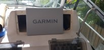
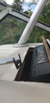
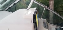
All done. Its actually going to fit with no modification to the deck above the console. I’m going to go to the plastic fabricator tomorrow and see what he can make. I’m thinking black acrylic to match the overhead console and what was originally there. Initially I thought I was going with a seafoam Starboard but I think the black will look better but open to thoughts\suggestions.
 

SkunkBoat

Well-Known Member
Joined
Oct 12, 2017
Messages
4,508
Reaction score
1,614
Points
113
Location
Manasquan Inlet NJ
Website
www.youtube.com
Model
Express 265
just a heads up. there is no wiggle room with those mounting holes. Once you have the cutout in the plexi, the holes are very close to the edge. I tried usung 3/16 plexi and it cracked. I ended up with 1/2" black Starboard. I like the starboard better because there is no reflection. The plexi was like a mirror.
 

Richard1572

GreatGrady Captain
Joined
Apr 26, 2008
Messages
59
Reaction score
9
Points
8
Location
Homestead, FL
Model
Sailfish
Thanks. Headed to the plasic guy shortly. We'll see what materials he has in stock and what he recommends.
 

Richard1572

GreatGrady Captain
Joined
Apr 26, 2008
Messages
59
Reaction score
9
Points
8
Location
Homestead, FL
Model
Sailfish
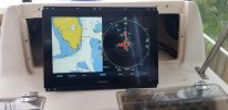
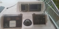
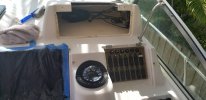
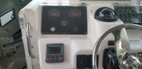
Well, all finished. I screwed up big time with the console template in the top left corner but it works for now. I had to button up the job as I have multi day fishing trips planned for every weekend in December except this weekend so I need to use this weekend to test everything out. Overall, it turned out good except for the shape of the dash panel. I'll have it redone when I put in the new switch panel sometime next year.

Based on a previous comment about how close the screws need to be to the edge causing the panel to crack, I just made a Starboard backer plate to screw into instead of the tiny lips in the existing console. I think it will be plenty sturdy that way and be much less likely to crack.

I replaced the compass and discovered something I found strange. The compass light, which was nonfunctional, was getting its power from the fuel gauge, which meant it turned on when you turned on the starboard engine. I thought it would be better if the compass light got its power from the nav lights so I changed that power source.

I installed a new panel for the gauges and added a couple of things. (1) The reset switch for the wireless tether (port side silver button) and (2) USB charging ports (Starboard side bottom right). I also reinforced this panel by adding starboard backing plates for the screws.

The switch panel is a project for next year but I read on this forum to give penetrol a try to make it look better and it does a pretty good job. One friend who looked at it thought I had replaced the switch panel too. Not sure how long it will last but I could always give a wipe down with some more penetrol.

Another electrical change I made was the spreader lights switch. Previously it was on the dome light and had then been moved to a switch up in the overhead console when the dome light was replaced. I moved that power source to an unused accessory switch on the dash panel. It works well but does actually have an impact on the compass. When I switch on the spreader light the compass moves by about 5 degrees. I guess the high current draw causes some magnetic deviation or something. Not a big deal as really the spreader lights are used, at least by me, mostly when loading the boat in the dark or at the dock, not when running and trying to follow a compass heading.

Overall, I consider the project a success. Plus, I now have a working knowledge of NEMA 2000, Garmin Network and I removed a full contractor garbage bag of unused cables and wires from the boat. Total investment including the electronics, the new compass and plastic fabrication was under $6k. The Garmin electronics included GPSMAP 1243xsv, GMR 18 xHD Radar, 2 X GFS10 Fuel Sensors, GT51M-TM DV/SV/600w CHIRP Transducer and a NEMA starter kit. On to the next project.20211022_083431(2).jpg20211114_104225.jpg20211114_104215(1).jpg20211115_121504.jpg20211128_120743(1).jpg20211201_172941.jpg20211201_172950.jpg20211201_173013.jpg20211201_173040.jpg
 
  • Like
Reactions: SkunkBoat